Arduino SPWM Generator Circuit – Code Details and Diagram
In this post we learn how to generate sine wave pulse-width-modulation or SPWM through Arduino, which can be used for making a pure sine wave inverter circuit or similar gadgets.
The Arduino code is developed by me, and it is my first Arduino code, ...and it looks pretty good 🙂
Basically, SPWM which stands for sine wave pulse width modulation, is a type of pulse modulation where the pulses are modulated to simulate a sinusoidal waveform, so that the modulation is able to attain properties of a pure sine wave.
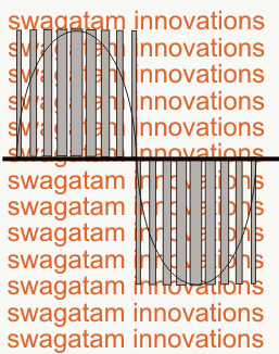
To implement a SPWM the pulses are modulated with an initial narrower widths which gradually get broader at the center of the cycle, and finally end being narrower at the end to finish the cycle.
To be more precise, the pulses begin with narrowest widths which gradually get broader with each subsequent pulses, and gets broadest at the center pulse, after this, the sequence continues on but with an opposite modulation, that is the pulses now gradually begin getting narrower until the cycle finishes.
Video Demo
This constitutes one SPWM cycle, and this repeats throughout at a particular rate as determined by the application frequency (usually 50Hz or 60Hz). Typically, SPWM is used for driving power devices such as mosfets or BJTs in inverters or converters.
This special modulation pattern ensures that the frequency cycles are executed with a gradually changing average voltage value (also called the RMS value) , instead of throwing sudden Hi/low voltage spikes as normally witnessed in flat square wave cycles.
This gradually modifying PWMs in a SPWM is purposely enforced so that it closely replicates the exponentially rising/falling pattern of a standard sinewaves or sinusoidal waveform, hence the name sinewave PWM or SPWM.
Generating SPWM with Arduino
The above explained SPWM can be easily implemented using a few discrete parts, and also using Arduino which will probably enable you to get more accuracy with the waveform periods.
The following Arduino code can be used for implementing the intended SPWM for a given application.
Gosh!! that looks awfully big, if you know how to shorten it, you may certainly feel free to do it at y;
In the next post I'll explain how to use the above Arduino based SPWM generator to make a pure sinewave inverter circuit....keep reading!
No comments:
Post a Comment