Sunday, May 17, 2020
Friday, April 17, 2020
How to program microcontroller
Programming languages and software for 8051 microcontroller
By Jestine Yong on March 10, 2016
In this article I will explain to you the programming languages used in microcontroller, software used to simulate the circuit and burner used to write the code in microcontroller ROM.
1: Programming Languages: Assembly, C++ and C Programming languages are used for the Microcontrollers. We can write code only in assembly language, only in C language or it can be mix of Assembly and C Language. Assembly Language is more close to the machine language but little bit difficult to use for the human. But C language is more easy for human. As Processors only know 0 or 1 so the code we write should be converted to the Hex file. Most famous software that is used for programming is KEIL. It’s a freeware software can be downloaded from the official website: www.keil.com
Download and install this software. Now check how to take start with this software.
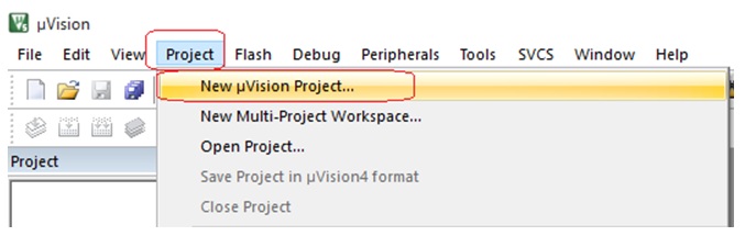
Open the software and click on project and select “new µvision project”
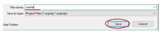
Now select your folder where you want to save file and then choose the project name and click on “save”
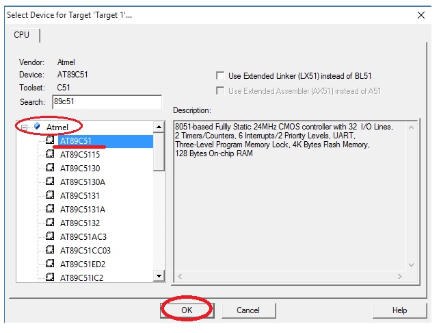
Now a new window will open. Here you have to choose your controller’s Brand and model. 8051 microcontrollers are made by Atmel and in this example we are using the Atmel 89c51. After choose the controller click on “OK”. After click on OK it will ask to start with file.a51 just select here NO.
Now just click on the “+” Button on Target and right click on source group and select “add new file to the group”
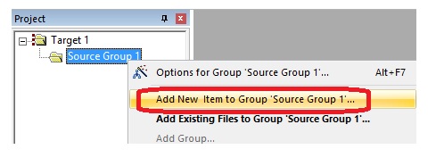
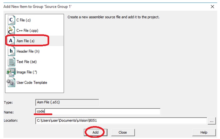
Here it will ask to select the file type that you have to create and file name. If you want to make program in Assembly Language you have to choose “Asm File”, for C Language “C File” and for C++ Language “C++ File”. First we start with Assembly Language. So select “Asm File” and click on “Add” button.
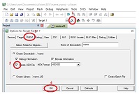
In default software is not selected to create “Hex” file. As we required “Hex” file so we have to configure it. See in figure below.
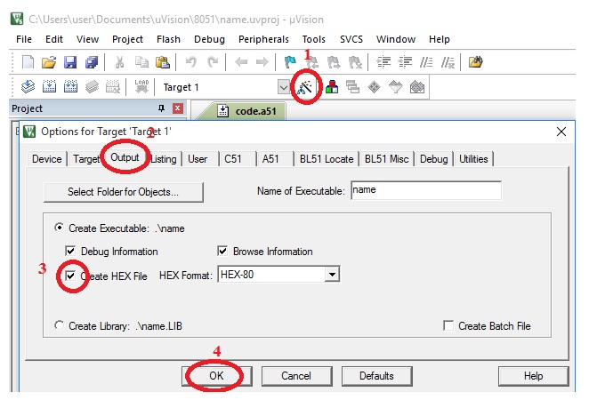
From this we have configured the target file. Now we write the simple code for microcontroller in Assembly Language.
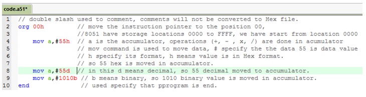
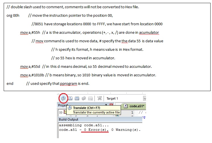
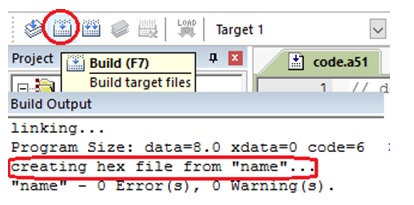
By clicking on translate button you can check if there is any error in code. If there is not error, then click on “build” button it will create “hex” file.
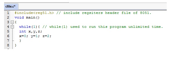
For C language programming in box where we were select “Asm File” just select “C File” and write code. Lets write code in C Language.
=======================================
#include<reg51.h> // include registers header file of 8051.
void main()
{
while(1){ // while(1) used to run this program unlimited time.
int x,y,z;
x=0; y=1; z=2;
}
}
====================================
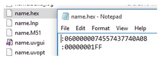
Now have a look of “hex file” that will be upload in the microcontroller’s ROM
Thank you.

This article was prepared for you by Hafiz Abdul Haseeb Tariq from FAST-National University of Computer and Emerging Sciences-Pakistan. He’s an Electronics & Embedded system engineer and has practical experience in circuit designing, networking, assembling, PCB making, 8051 & Arduino programming.
Programming languages and software for 8051 microcontroller
By Jestine Yong on March 10, 2016
In this article I will explain to you the programming languages used in microcontroller, software used to simulate the circuit and burner used to write the code in microcontroller ROM.
1: Programming Languages: Assembly, C++ and C Programming languages are used for the Microcontrollers. We can write code only in assembly language, only in C language or it can be mix of Assembly and C Language. Assembly Language is more close to the machine language but little bit difficult to use for the human. But C language is more easy for human. As Processors only know 0 or 1 so the code we write should be converted to the Hex file. Most famous software that is used for programming is KEIL. It’s a freeware software can be downloaded from the official website: www.keil.com
Download and install this software. Now check how to take start with this software.
Open the software and click on project and select “new µvision project”
Now select your folder where you want to save file and then choose the project name and click on “save”
Now a new window will open. Here you have to choose your controller’s Brand and model. 8051 microcontrollers are made by Atmel and in this example we are using the Atmel 89c51. After choose the controller click on “OK”. After click on OK it will ask to start with file.a51 just select here NO.
Now just click on the “+” Button on Target and right click on source group and select “add new file to the group”
Here it will ask to select the file type that you have to create and file name. If you want to make program in Assembly Language you have to choose “Asm File”, for C Language “C File” and for C++ Language “C++ File”. First we start with Assembly Language. So select “Asm File” and click on “Add” button.
In default software is not selected to create “Hex” file. As we required “Hex” file so we have to configure it. See in figure below.
From this we have configured the target file. Now we write the simple code for microcontroller in Assembly Language.
By clicking on translate button you can check if there is any error in code. If there is not error, then click on “build” button it will create “hex” file.
For C language programming in box where we were select “Asm File” just select “C File” and write code. Lets write code in C Language.
=======================================
#include<reg51.h> // include registers header file of 8051.
void main()
{
while(1){ // while(1) used to run this program unlimited time.
int x,y,z;
x=0; y=1; z=2;
}
}
====================================
Now have a look of “hex file” that will be upload in the microcontroller’s ROM
Thank you.
This article was prepared for you by Hafiz Abdul Haseeb Tariq from FAST-National University of Computer and Emerging Sciences-Pakistan. He’s an Electronics & Embedded system engineer and has practical experience in circuit designing, networking, assembling, PCB making, 8051 & Arduino programming.
Wednesday, April 1, 2020
Tuesday, March 31, 2020
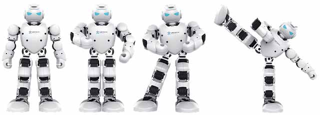
Humanoid robots
Time waits for none. Apparently, it's the same case with the speed of Technology upgrade these days. Moore's law is already broken. The happening innovation keeps us wondering 'how amazing it is' and 'what's next' at the same time. Since always, Advancements in technology are inspired by Science Fiction and action movies for implementing the fictional gadgets into reality. On 26th October 2017, a gynoid ‘Sophia’ with state of the art artificial intelligence was given citizenship of Saudi Arabia. Who would have thought of this event would be possible when we saw C-3PO in ‘Star Wars’ movie Franchise as one of the first and most memorable humanoid robot characters ever seen in the movies.
What is a Humanoid Robot?
Humanoids are the robots which are designed as to look like humans. Why Humans? Well, robots are created by humans to reduce the repetitive manual work which was previously done by them. So why not design it like humans. Let us not forget, humans have evolved over time and again since millions of years in the first place. This human type design provides better grip for regular tasks, better awareness of obstacles and better interaction with humans. Most importantly, it is proved immensely helpful for biological advancements in the human body. You can find all kinds of robotic applications available from DIY to Integrated with our nervous system. The more it amazes you, the costlier it gets. If you go for most advanced, just a limb can cost you a hundred thousand dollars.
In the initial years, it was only thought for automating repetitive manual in the industrial sector. It was implemented and working fine for a long time now. After the advancements in biological engineering, hopes in the consumer sector gained momentum. Today, after the introduction of artificial intelligence (AI), the scenario has taken a drastic upside turn for the scope and advancements in this field. After the integration of AI, it is practically a Human being. It doesn’t only look like a Human being but it has its own thought process, own strategic thinking ability and although they may not be able to feel, but it can acknowledge the possible emotion as well.
Unmanned robots have already found their way into applications in our day to day lives. Recently, it made its debut as an Olympic Torchbearer in South Korea. Although most of these robots contribute to Floor Cleaning Robots, they have acquired their place in every segment of tedious work done by humans. Now, as humans can be a major threat to mankind, Debates have come up with a swirl on whether AI can be a threat to mankind as well. These two have amalgamated so well that there’s nothing wrong in saying that now the words ‘Humanoid Robots’ and ‘Artificial Intelligence’ go hand in hand.
Today, we have a wide range of Robots available in the market from ₹4000 to whatever you can pour in. However, the best one will be the one created by you yourself. It covers best of both worlds, Electronics and Computer engineering and gives you a product which is a peerless example of how innovation happens at the edge of two different domains. Let’s see how basics are used to create one of the leading advancements in the world today.
Robots like Humans:
We will first understand that how the mechanics of our body and robots can be very similar to a very common and easy DIY Experiment.
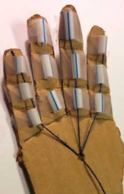
DIY Basic hand:
You need 4 straws, Cardboard Plank, Glue, Scissors and 10m Thread reel
Cut the card in the shape of a Hand i.e. Arm extension into four fingers. (Let us ignore thumb for now). Fold all four finger extensions on cardboard such that it forms two joints and three phalanges on each finger. Now cut the straw and glue them on each phalanx. Make sure their size is smaller than their respective phalanx. Now cut the thread into four parts and pass it through each of these fingers. One end of the thread should be fixed at the open end of the finger while the other end of the all four pieces should be tied together. Your basic hand is ready. Now, when you hold the cardboard hand from the position of the wrist and pull the Knot where it is tied together, you can see the four fingers bend in the motion just like our hand when we grip something. You can see for yourself how individual fingers by pulling individual threads instead of the knot as well. You have created one of the most basic robotic arm architecture.
What did we learn from this architecture? Notice how each finger has its own thread to get pulled, see a single pull gives motion to each phalanx one by one and when we need to use multiple fingers, just pull all together and note that each work together. Their action might be delayed and each finger may form curve at different speeds as we are pulling different length of the fingers with the same force, from the same point.
These are some of the small things which are taken into the consideration while making each part of the limbs and also the torso. This is proved helpful for the people with disabilities, without an actual limb. The nerve used for moving any of the fingers must be passing from the upper hand. For someone whose arm is only till the ankle, sensory cords are connected to the lower part of the upper arm and an electronic armature is created to move with respect to the motion of the muscle at that lower part of the arm. This way, one can have an arm controlled by our brains just like any other arm.
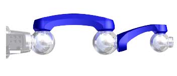
These aren’t exactly the types of machines used these days. Today, we have Robotic to Human size ratio of 1:1. The latest arms are equipped with synchronous motors which are used for simultaneous movements with single instruction. But for machineries and repetitive manual work, most widely used structure is Six-axis Powerball arm. They are made of 3 Ball joints, 5 joints overall; one ball joint can be considered as a shoulder joint, another ball joint will replace the ankle while the last ball joint forms the wrist. The rest of the structure can be considered as upper and lower arm structure which provides strength to the arm structure. It is created in such a way that it can cover all the area in its outreach, unlike our hand. For example, you cannot bend your hand in the backward direction from the ankle but this structure can do turn in every direction; the only limit is its length.
Legs in a Humanoid Robot:
The joints are same as hand but instead of hand architecture, we can use hoverboard kind of architecture as it would be the most convenient one for its movement from one place to another. Although it’s lower body as well as upper body, especially the limbs are created as per the requirements and the purpose for what it’s made and hence, Hoverboard architecture is rarely used for the lower limbs. They are been made to be same as humans internally as well as externally. The artificial Rib cage is used for its Torso part which gives protection to the internal circuit and mechanics. Legs are created to duplicate the maneuver just like human legs.
Other Devices in Humanoids:
Other minimal device requirements for creating a Humanoid are HD Cameras, which will help collect data for Image processing, RFID, which will help give us instructions remotely, IR Sensors, to detect obstacle, humans, and distance from them, Rotors, for their movement, Accelerometer, Magnetometer, Gyroscope and Ethernet connection for controlling the movement if needed, A CPU, A Battery Unit, A PLC is must for regulated outputs and designing the logic.
Main Applications of Humanoids:
There are unlimited possibilities with robots and humanoids from doing a repeated manual task, to think and take a decision using Artificial Intelligence. Here I am mentioning few main areas where Humanoids are used:
Personal Home Assistants:
Integrating IoT with these robots will create a personal Home assistant which manages your Electricity, Light, Sound, and Temperature at your home using your home automation system.

Virtual Reality:
Integrating Virtual Reality with these robots and programming them to replicate our motion movements will give you a replica of yourself which will be useful in Fire, Flood, Experimentation or other dangerous situation where human life can be at stake. We can find all kinds of application of this futuristic bots but let’s discuss the most important one. The one which will be the most helpful for the people in need: Prosthetics.
Prosthetics:
Prosthetics is one of the main reasons why it is made to look like actual body parts. Humanoids can be used a transplant or a replacement of a body part which will be connected to the nervous system of the body. A person without hand after elbow can make the hand customized for oneself to be connected to the nerves below the upper arm near the shoulder. Each nerve movement and extension of the inner part of the upper arm will give a unique signal to the brain. This signal will be corresponding to a specific hand movement; the modular prosthetic limb will recognize the muscle pattern and movement in the hand will take place accordingly. Not to forget that each of these things will happen in real time. Just by the trigger of a thought, you can move the hand just like it is your own hand. It will change the way special people live. It will be helpful for the people who went through an accident and lost a limb or other body part. The best technology available today also has over 100 sensors in the palm itself, providing sensation capabilities of an actual touch on the surface of the artificial arms and legs which provides successful targeted sensory innervation and feel.
 Mind Controlled Prosthetic Arm developed by DEKA Research & Development Corp
The creation and advancements of this Humanoid Robots are never-ending. Major innovations and breakthroughs happen every day in this very field. Numerous applications from industrial to now in our day to day life direct the trend of these droids to keep up and turn upwards. Multiple jobs will be replaced by robots in near future. This issue is debated in the parliaments around the world. The idea of ‘Basic income for everyone’ was introduced as one of the options while keeping the recessions and unemployment in mind. The government of several countries has shown resistance and placed their thoughts about putting a ban on AI while some of the governments showed interest in restriction of the applications of humanoid robots and them replacing the jobs.
The importance of these products can be easily seen with the surge of the issues, merits, and demerits being discussed in the houses. One thing is for sure, with the mixture of best in the class software of Artificial Intelligence and these best in class physical structures of circuitry, the product which is known is going to take over the world very fast even with any restrictions. And the development of these kinds of Humanoids has already started, as we can see the Sophia Robot as the great example of Artificial Intelligence with perfect human physical structure.
Bare minimum Arduino
Bare Minimum code needed
This example contains the bare minimum of code you need for a sketch to compile properly on Arduino Software (IDE): the
setup() method and the loop() method.Hardware Required
- Arduino or Genuino Board
Circuit
Only your Arduino or Genuino Board is needed for this example.

image developed using Fritzing . For more circuit examples, see the Fritzing project page
Code
The
setup() function is called when a sketch starts. Use it to initialize variables, pin modes, start using libraries, etc. The setup function will only run once, after each powerup or reset of the board.
After creating a
setup() function, the loop()function does precisely what its name suggests, and loops consecutively, allowing your program to change and respond as it runs. Code in theloop() section of your sketch is used to actively control the board.
The code below won't actually do anything, but it's structure is useful for copying and pasting to get you started on any sketch of your own. It also shows you how to make comments in your code.
Any line that starts with two slashes (//) will not be read by the compiler, so you can write anything you want after it. The two slashes may be put after functional code to keep comments on the same line. Commenting your code like this can be particularly helpful in explaining, both to yourself and others, how your program functions step by step.
void setup ( ) {
// put your setup code here, to run once:
}
void loop ( ) {
// put your main code here, to run repeatedly:
}
// put your setup code here, to run once:
}
void loop ( ) {
// put your main code here, to run repeatedly:
}
Using ADC module of pic microcontroller
In this tutorial, we will learn How to Use ADC with our PIC microcontroller PICF877A. Most of the Microcontroller projects will involve an ADC (Analog to Digital converter) in it, because it is one the most used ways to read data from the real world. Almost all the sensors like temperature sensor, flux sensor, pressure sensor, current sensors, voltage sensors, gyroscopes, accelerometers, distance sensor, and almost every known sensor or transducer produces an analog voltage of 0V to 5V based on the sensors reading. A temperature sensor for instance may give out 2.1V when the temperature is 25C and go upto 4.7 when the temperature is 60C. In order to know the temperature of the real world, the MCU has to just read the output voltage of this temperature sensor and relate it to the real world temperature. Hence ADC is an important work tool for MCU projects and lets learn how we can use it on our PIC16F877A.
ADC in PIC Microcontroller PIC16F877A:
There are many types of ADC available and each one has its own speed and resolution. The most common types of ADCs are flash, successive approximation, and sigma-delta. The type of ADC used in PIC16F877A is called as the Successive approximation ADC or SAR in short. So let’s learn a bit about SAR ADC before we start using it.
Successive Approximation ADC: The SAR ADC works with the help of a comparator and some logic conversations. This type of ADC uses a reference voltage (which is variable) and compares the input voltage with the reference voltage using a comparator and difference, which will be a digital output, is saved from the Most significant bit (MSB). The speed of the comparison depends on the Clock frequency (Fosc) on which the PIC is operating.
Now that we know some basics on ADC, lets open our datasheet and learn how to use the ADC on our PIC16F877A MCU. The PIC we are using has 10-bit 8-channel ADC. This means the output value of our ADC will be 0-1024 (2^10) and there are 8 pins (channels) on our MCU which can read analog voltage. The value 1024 is obtained by 2^10 since our ADC is 10 bit. The eight pins which can read the analog voltage are mentioned in the datasheet. Lets look at the picture below.
The analog channels AN0 to AN7 are highlighted for you. Only these pins will be able to read analog voltage. So before reading an input voltage we have to specify in our code which channel has to be used to read the input voltage. In this tutorial we will use channel 4 with a potentiometer to read the analog voltage at this channel.
The A/D module has four registers which has to be configured to read data from the Input pins. These registers are:
• A/D Result High Register (ADRESH)
• A/D Result Low Register (ADRESL)
• A/D Control Register 0 (ADCON0)
• A/D Control Register 1 (ADCON1)
Programming for ADC:
The program for using ADC with PIC Microcontroller is very simple, we just have to understand these four registers and then reading any analog voltage will be simple. As usual initialize the configuration bits and let’s start with the void main().
Inside the void main() we have to initialize our ADC by using the ADCON1 register and ADCON0 register. The ADCON0 register has the following bits:
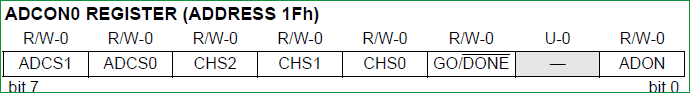
In this register we have to turn on the ADC module by making ADON=1 and turn on the A/D Conversion Clock by using the bits ADCS1 and ADCS0 bits, the rest will not be set for now. In our program the A/D conversion clock is selected as Fosc/16 you can try your own frequencies and see how the result changes. Complete details available on datasheet’s page 127. Hence ADCON0 will be initialised as follows.
ADCON0 = 0b01000001;
Now the ADCON1 register has the following bits:
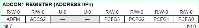
In this register we have to make A/D Result Format Select bit high by ADFM=1 and make ADCS2 =1 to select the Fosc/16 again. The other bits remain zero as we have planned to use the internal reference voltage. Complete details available on datasheet page 128. Hence ADCON1 will we set as follows.
ADCON1 = 0x11000000;
Now after initializing the ADC module inside our main function, lets get into the while loop and start reading the ADC values. To read an ADC value the following steps has to be followed.
- Initialize the ADC Module
- Select the analog channel
- Start ADC by making Go/Done bit high
- Wait for the Go/DONE bit to get low
- Get the ADC result from ADRESH and ADRESL register
1. Initialize the ADC Module: We have already learnt how to initialize an ADC so we just call this below function to initialize the ADC
The void ADC_Initialize() function is be as follows.
void ADC_Initialize()
{
  ADCON0 = 0b01000001; //ADC ON and Fosc/16 is selected
  ADCON1 = 0b11000000; // Internal reference voltage is selected
}
2. Select the analog channel: Now we have to select which channel we are going to use to read the ADC value. Lets make a function for this, so that it will be easy for us to shift between each channel inside the while loop.
unsigned int ADC_Read(unsigned char channel)
{
    //****Selecting the channel**///
  ADCON0 &= 0x11000101; //Clearing the Channel Selection Bits
  ADCON0 |= channel<<3; //Setting the required Bits
  //**Channel selection complete***///
}
Then channel to be selected is received inside the variable channel. In the line
ADCON0 &= 0x1100101;
The previous channel selection (if any) is cleared. This is done by using the bitwise and operator “&”. The bits 3, 4 and 5 are forced to be 0 while the others are left to be in their previous values.
Then the desired channel is selected by left shifting the channel number thrice and setting the bits using the bitwise or operator “|”.
ADCON0 |= channel<<3; //Setting the required Bits
3. Start ADC by making Go/Done bit high: Once the channel is selected we have to start the ADC conversion simply by making the GO_nDONE bit high:
GO_nDONE = 1; //Initializes A/D Conversion
4. Wait for the Go/DONE bit to get low: The GO/DONE bit will stay high until the ADC conversion has been completed, hence we have to wait till this bit goes low again. This can be done by using a whileloop.
while(GO_nDONE); //Wait for A/D Conversion to complete
Note: Placing a semi-colon next to while will make the program to be held there till the condtion of the while loop is false.
5. Get the ADC result from ADRESH and ADRESL register: When the Go/DONE bit gets low again it means that the ADC conversion is complete. The result of the ADC will be a 10-bit value. Since our MCU is a 8-bit MCU the result is split into upper 8-bit and the lower 2-bits. The upper 8-bit result is stored in the register ADRESH and the lower 2-bit is stored in the register ADRESL. Hence we have to add up these to registers to get our 10-bit ADC value. This result is returned by the function as shown below:
return ((ADRESH<<8)+ADRESL); //Returns Result
The complete function which is used to select the ADC channel, trigger the ADC and return the result is shown here.
unsigned int ADC_Read(unsigned char channel)
{
  ADCON0 &= 0x11000101; //Clearing the Channel Selection Bits
  ADCON0 |= channel<<3; //Setting the required Bits
  __delay_ms(2); //Acquisition time to charge hold capacitor
  GO_nDONE = 1; //Initializes A/D Conversion
  while(GO_nDONE); //Wait for A/D Conversion to complete
  return ((ADRESH<<8)+ADRESL); //Returns Result
}
Now we have a function which will take the channel selection as input and return us the ADC value. Hence we can directly call this function inside our while loop, since we are reading the analog voltage from channel 4 in this tutorial, the function call will be as follows.
i = (ADC_Read(4)); //store the result of adc in “i”.
In order to visualize the output of our ADC we will be needing some sort of display modules like the LCD or the 7-segment.
The complete code is given below and the process is also explained in the Video at the end.
Hardware Setup and Testing:
As usual simulate the code using Proteus before actually go with our hardware, the schematics of the project is shown below:

Connections of 4-digit seven segment display module with PIC microcontroller are same as the previous project, we have just added a potentiometer to the pin 7 which is the analog channel 4. By varying the pot, a variable voltage will be sent to the MCU which will be read by the ADC module and displayed on the 7-segment display Module.
Here we have used the same PIC Microcontroller board which we have created in LED blinking Tutorial. After ensuring connection upload the program into PIC and you should see an output like this
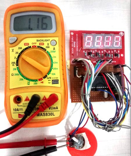
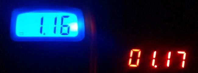
Here we have read the ADC value from the pot and converted it to the actual voltage by mapping the 0-1024 output as 0-5 volts (as shown in program). The value is then displayed on the 7-segment and verified using the multimeter.
Thats it, now we are ready to use all the Analog Sensors available in the market, go ahead and try this and if you have any problems as usual use the comment section, we will be happy to help you out.
Code:
// CONFIG
#pragma config FOSC = HS // Oscillator Selection bits (HS oscillator)
#pragma config WDTE = OFF // Watchdog Timer Enable bit (WDT disabled)
#pragma config PWRTE = ON // Power-up Timer Enable bit (PWRT enabled)
#pragma config BOREN = ON // Brown-out Reset Enable bit (BOR enabled)
#pragma config LVP = OFF // Low-Voltage (Single-Supply) In-Circuit Serial Programming Enable bit (RB3 is digital I/O, HV on MCLR must be used for programming)
#pragma config CPD = OFF // Data EEPROM Memory Code Protection bit (Data EEPROM code protection off)
#pragma config WRT = OFF // Flash Program Memory Write Enable bits (Write protection off; all program memory may be written to by EECON control)
#pragma config CP = OFF // Flash Program Memory Code Protection bit (Code protection off)
// #pragma config statements should precede project file includes.
// Use project enums instead of #define for ON and OFF.
// Use project enums instead of #define for ON and OFF.
#include <xc.h>
#define _XTAL_FREQ 20000000
#define _XTAL_FREQ 20000000
//***Define the signal pins of all four displays***//
#define s1 RC0
#define s2 RC1
#define s3 RC2
#define s4 RC3
//***End of definition**////
#define s1 RC0
#define s2 RC1
#define s3 RC2
#define s4 RC3
//***End of definition**////
void ADC_Initialize()
{
ADCON0 = 0b01000001; //ADC ON and Fosc/16 is selected
ADCON1 = 0b11000000; // Internal reference voltage is selected
}
{
ADCON0 = 0b01000001; //ADC ON and Fosc/16 is selected
ADCON1 = 0b11000000; // Internal reference voltage is selected
}
unsigned int ADC_Read(unsigned char channel)
{
ADCON0 &= 0x11000101; //Clearing the Channel Selection Bits
ADCON0 |= channel<<3; //Setting the required Bits
__delay_ms(2); //Acquisition time to charge hold capacitor
GO_nDONE = 1; //Initializes A/D Conversion
while(GO_nDONE); //Wait for A/D Conversion to complete
return ((ADRESH<<8)+ADRESL); //Returns Result
}
void main()
{ int a,b,c,d,e,f,g,h,adc; //just variables
int i = 0; //the 4-digit value that is to be displayed
int flag =0; //for creating delay
{ int a,b,c,d,e,f,g,h,adc; //just variables
int i = 0; //the 4-digit value that is to be displayed
int flag =0; //for creating delay
unsigned int seg[]={0X3F, //Hex value to display the number 0
0X06, //Hex value to display the number 1
0X5B, //Hex value to display the number 2
0X4F, //Hex value to display the number 3
0X66, //Hex value to display the number 4
0X6D, //Hex value to display the number 5
0X7C, //Hex value to display the number 6
0X07, //Hex value to display the number 7
0X7F, //Hex value to display the number 8
0X6F //Hex value to display the number 9
}; //End of Array for displaying numbers from 0 to 9
//*****I/O Configuration****//
TRISC=0X00;
PORTC=0X00;
TRISD=0x00;
PORTD=0X00;
//***End of I/O configuration**///
TRISC=0X00;
PORTC=0X00;
TRISD=0x00;
PORTD=0X00;
//***End of I/O configuration**///
ADC_Initialize();
#define _XTAL_FREQ 20000000
while(1)
{
if(flag>=50) //wait till flag reaches 100
{
adc = (ADC_Read(4));
i = adc*0.488281;
flag=0; //only if flag is hundred "i" will get the ADC value
}
flag++; //increment flag for each flash
{
if(flag>=50) //wait till flag reaches 100
{
adc = (ADC_Read(4));
i = adc*0.488281;
flag=0; //only if flag is hundred "i" will get the ADC value
}
flag++; //increment flag for each flash
//***Splitting "i" into four digits***//
a=i%10;//4th digit is saved here
b=i/10;
c=b%10;//3rd digit is saved here
d=b/10;
e=d%10; //2nd digit is saved here
f=d/10;
g=f%10; //1st digit is saved here
h=f/10;
//***End of splitting***//
a=i%10;//4th digit is saved here
b=i/10;
c=b%10;//3rd digit is saved here
d=b/10;
e=d%10; //2nd digit is saved here
f=d/10;
g=f%10; //1st digit is saved here
h=f/10;
//***End of splitting***//
PORTD=seg[g];s1=1; //Turn ON display 1 and print 4th digit
__delay_ms(5);s1=0; //Turn OFF display 1 after 5ms delay
PORTD=seg[e];RD7=1;s2=1; //Turn ON display 2 and print 3rd digit
__delay_ms(5);s2=0; //Turn OFF display 2 after 5ms delay
PORTD=seg[c];s3=1; //Turn ON display 3 and print 2nd digit
__delay_ms(5);s3=0; //Turn OFF display 3 after 5ms delay
PORTD=seg[a];s4=1; //Turn ON display 4 and print 1st digit
__delay_ms(5);s4=0; //Turn OFF display 4 after 5ms delay
}
}
Subscribe to:
Posts (Atom)