please subscribe comment and share
https://youtu.be/oxYSvvplxYU
Inverter circuits are often needed where it is not possible to get AC supply from the grid. An inverter circuit is used to convert DC power to AC power and it can be divided into two types that is Pure Sine Wave Inverters or Modified Square Wave Inverters. These pure sine wave inverters are very expensive, where the modified square wave inverters are inexpensive. Learn more about different types of inverter here.
In a previous article, I have shown you how not to make a modified square wave inverter by addressing the problems associated with it. So in this article, I will be making a simple pure sine wave inverter using Arduino, and explain the working principle of the circuit.
If you are making this circuit, please note that this circuit features no feedback, no overcurrent protection, no short circuit protection, and no temperature protection. Hence this circuit is built and demonstrated for educational purposes only, and it’s absolutely not recommended to build and use this type of circuit for commercial appliances. However you can add them to your circuit if required, the commonly used protection circuits like
Over Voltage Protection, Overcurrent Protection, Reverse polarity Protection, Short Circuit Protection, Hot Swap controller, etc. have already been discussed.
CAUTION: If you are making this type of circuit, please be extra careful about high voltage and voltage spikes generated by the switching signal to the input.
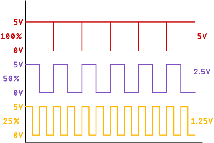
As the name suggests, SPWM stands for Sinusoidal Pulse Width Modulation. As you may already know, a PWM signal is a signal in which we can change the frequency of the pulse as well as the on-time and off-time, which is also known as the duty cycle. If you want to learn more about PWM, you can read it here. So, by varying the duty cycle, we alter the average voltage of the pulse. The image below shows that-
If we consider a PWM signal which is switching in between 0 - 5V which has a duty cycle of 100%, we will get an average output voltage of 5V, again if we consider the same signal with a duty cycle of 50%, we will get the output voltage of 2.5V, and for the duty cycle of 25%, it's half of that. That sums up the basic principle of the PWM signal, and we can move onto understanding the basic principle of the SPWM signal.
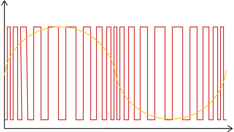
A sine voltage is primarily an analogy voltage which alters its magnitude over time, and we can reproduce this behaviour of a sine wave by continually changing the duty cycle of the PWM wave, the below image shows that.
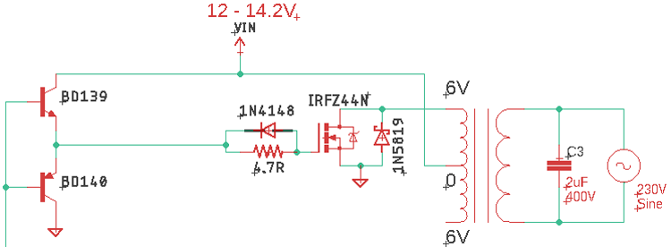
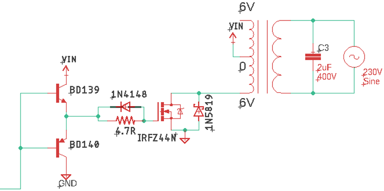
If you look at the schematic below, it will see there is a capacitor connected at the output of the transformer. This capacitor is responsible for smoothing out the AC signal from the carrier frequency.
The utilized input signal will charge and discharge the capacitor according to the input signal and load. As we have used a very high-frequency SPWM signal, it will have a very small duty cycle which is like 1%, this 1% duty cycle will charge the capacitor a little, the next duty cycle is 5%, this will again charge the capacitor a little more, following pulse will have a duty cycle of 10% and the capacitor will charge a little bit more, we will apply the signal until we have reached a duty cycle of 100% and from there, we will go back down to 1%. This will create a very smooth curve like a sine wave at the output. So, by providing proper values of the duty cycle at the input, we will have a very sinusoidal wave at the output.
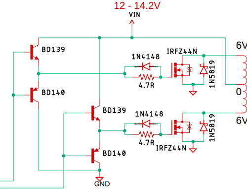
The above image shows the main driving section of the SPWM inverter, and as you can see, we have used two N-channel MOSFETs in half-bridge configuration to drive the transformer of this circuit, to reduce unwanted switching noise and to protect the MOSFET, we have used 1N5819 diodes parallel with the MOSFETs. To reduce any harmful spikes generated in the gate section, we have used the 4.7 ohms resistors parallel with 1N4148 diodes. Finally, the BD139 and BD 140 transistors are configured in a push-pull configuration to drive the gate of the MOSFET, because this MOSFET has a very high gate capacitance and requires a minimum of 10V at the base to turn on properly. Learn more about the working of Push-Pull amplifiers here.
To better understand the working principle of the circuit, we have reduced it to a point where this section of the MOSFET is ON. When the MOSFET is on the current, first flows through the transformer and then gets grounded by the MOSFET, thus a Magnetic flux will also be induced in the direction in which the current is flowing, and the core of the transformer will pass the magnetic flux in the secondary winding, and we will get the positive half cycle of the sinusoidal signal at the output.
In the next cycle, the bottom part of the circuit is on the top part of the circuit is off that is why I have removed the top part, now the current flows in the opposite direction and generates a magnetic flux in that direction, thus reversing the direction of the magnetic flux in the core. Learn more about the working of MOSFET here.
Now, we all know that a transformer works by magnetic flux changes. So, turning both the MOSFETs on and off, one inverted to another and doing that 50 times in a second, will generate a nice oscillating magnetic flux inside the core of the transformer and the changing magnetic flux will induce a voltage in the secondary coil as we know by the faraday's law. That is how the basic inverter works.
The complete SPWM inverter circuit used in this project is given below.
| Sl.No | Parts | Type | Quantity |
| 1 | Atmega328P | IC | 1 |
| 2 | IRFZ44N | Mosfet | 2 |
| 3 | BD139 | Transistor | 2 |
| 4 | BD140 | Transistor | 2 |
| 5 | 22pF | Capacitor | 2 |
| 6 | 10K,1% | Resistor | 1 |
| 7 | 16MHz | Crystal | 1 |
| 8 | 0.1uF | Capacitor | 3 |
| 9 | 4.7R | Resistor | 2 |
| 10 | 1N4148 | Diode | 2 |
| 11 | LM7805 | Voltage Regulator | 1 |
| 12 | 200uF,16V | Capacitor | 1 |
| 13 | 47uF, 16V | Capacitor | 1 |
| 14 | 2.2uF,400V | Capacitor | 1 |
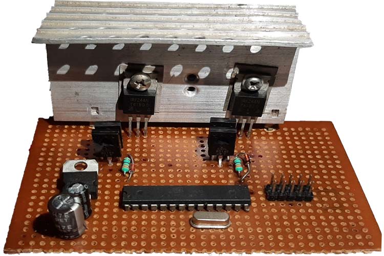
For this demonstration, the circuit is constructed on Veroboard, with the help of the schematic, At the output of the transformer, a huge amount of current will flow through the connection, so the connection jumpers need to be as thick as possible.
Before we go ahead and start to understand the code, let's clear out the basics. From the above working principle, you have learned how the PWM signal will look like at the output, now the question remains how we can make such a varying wave at the output pins of the Arduino.
To make the varying PWM signal, we are going to use the 16-bit timer1 with a prescaler setting of 1, which will give us 1600/16000000 = 0.1ms time for each count if we consider a single half-cycle of a sine wave, that fits exactly 100 times within a one-half cycle of the wave. In simple terms, we will be able to sample our sine wave 200 times.
Next, we have to divide our sine wave to 200 pieces and calculate their values with a correlation of the amplitude. Next, we have to convert those values to timer counter values by multiplying it with the counter limit. Finally, we have to put those values into a lookup table to feed it to the counter and we will get our sine wave.

Now a days the most advance solar charge controller are Maximum Power Point Tracking (MPPT). These controllers are more expensive than the PWM charge controllers, but it has several advantages in compare to. The MPPT charge controllers are used for extracting the maximum available power from solar panels for charging battery under certain conditions.
Of corse, you can buy one because to build one require some basic knowledge of electronics.
MPPT circuit is based around a synchronous buck converter circuit.
I shall not insist upon it. There are lot of knowledge on this site. A good job was made by Julian Ilett, who put a lot of youtube tutorials waiting for you.
First you can try one of that kind of converters and after a little encouragement and success you cant start an new project if you don`t keep reading the last one of these:
– Tim Nolan web archive page, with folowing link
–Arduino powered solar battery charger
–Arduino solar charge controller
–Arduino based MPPT solar charger controller
I thanks to all of them for sharing their knowledge. The first one is Tim Nolan who initiated this adventure. And I think you will not be the last who will try.
Now I can not tell you “Abandon all hope, ye who enter here.” but will not be so easy and you may try that just one more time in your life.
All of these enthusiasts was inspired me to build one, and finish this project.
In this page deba168 wrote on 29.07.2016: “I am no more working on this project due to some issues. This controller is not working.”
I think you wrong. Your project is living. Look at here. I have nothing to complain. I just made some little changes, et voila…

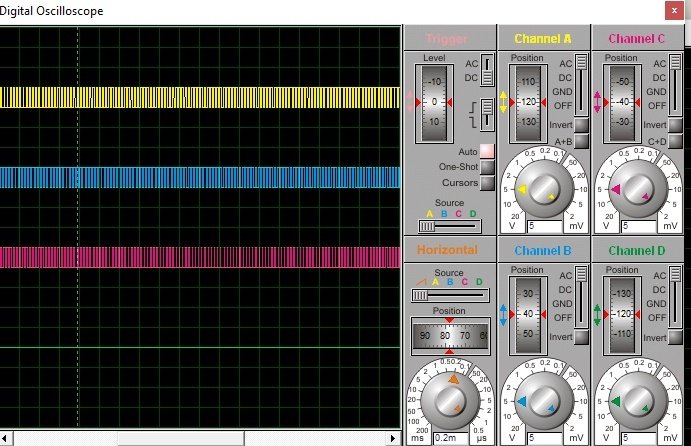
In the next image are the waveforms of input signals for the MOSFET`s and the output signal :
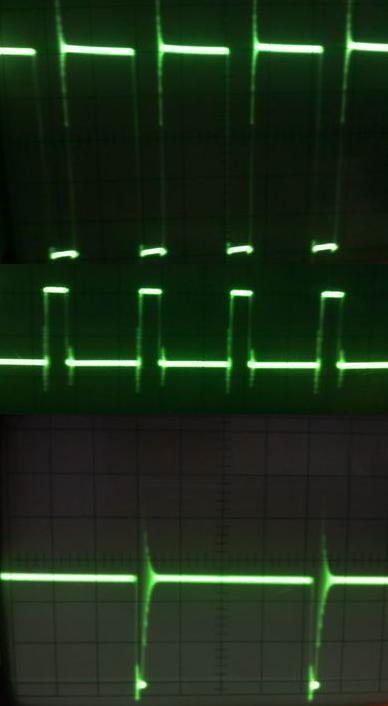
The waveforms are for 5V/div amplitude and 5 us/div timebase.
And this is the image of my functional MPPT Solar Charger powered by an Mono Crystalline Silicon PV Module, with a maximum power of 50W (maximum 21,5V / 3,5A) , for charging a 12 V lead acid battery:


The Arduino code is from from MPPT solar charger build around Tim Nolans open source MPPT solar prototype project updated by Debiasish Dutta in his website, that I made a couple of changes:
And this is the final project image:
 contact this number for the code +2348106009848
Designing an inverter transformer can be a complex affair. However, using the various formulas and by taking the help of one practical example shown here, the operations involved finally become very easy.
The present article explains through a practical example the process of applying the various formulas for making an inverter transformer.The various formulas required for designing a transformer has been already discussed in one my previous articles.Update: A detailed explanation can be also studied in this article: HOW to make transfomers
An inverter is your personal power house, which is able to transform any high current DC source into readily usable AC power, quite similar to the power received from your house AC outlets.
Although inverters are extensively available in the market today, but designing your own customized inverter unit can make you overwhelmingly satisfied and moreover it's great fun.
At Bright Hub I have already published many inverter circuit diagram, ranging from simple to sophisticated sine wave and modified sine wave designs.
However folks keep on asking me regarding formulas that can be easily used for designing a inverter transformer.
The popular demand inspired me to publish one such article dealing comprehensively with transformer design calculation. Although the explanation and the content was up to the mark, quite disappointingly many of you just failed to grasp the procedure.
This prompted me to write this article which includes one example thoroughly illustrating how to use and apply the various steps and formulas while designing your own transformer.
Let’s quickly study the following attached example:Suppose you want to design an inverter transformer for a 120 VA inverter using a 12 Volt automobile battery as the input and need 230 Volts as the output. Now, simply dividing 120 by 12 gives 10 Amps, this becomes the required secondary current.
Want to lead you how to design basic inverter circuit
In the following explanation the Primary Side is referred to as the Transformer side which may be connected at the DC Battery side, while the Secondary side signifies the Output AC 220V side.
The data in hand are:
Step#1: First we need to find the core area CA = 1.152 ×√ 24 × 10 = 18 sq.cm where 1.152 is a constant.
We select CRGO as the core material.
Step#2: Calculating Turns per Volt TPV = 1 / (4.44 × 10–4 ×18 × 1.3 × 50) = 1.96, except 18 and 50 all are constants.
Step#3: Calculating Secondary Current = 24 × 10 / 230 × 0.9 (assumed efficiency) = 1.15 Amps,
By matching the above current in Table A we get the approximate Secondary copper wire thickness = 21 SWG.
Step#5: Calculating Primary Number of Turns = 1.04 (1.96 × 24) = 49. The value 1.04 is included to ensure that a few extra turns are added to the total, to compensate for the winding losses.
Step#6: Calculating Primary Winding Area = 49 / 12.8 (From Table A) = 3.8 Sq.cm.
Therefore, the Total Winding Area Comes to = (3.27 + 3.8) × 1.3 (insulation area added 30%) = 9 sq.cm.
Step#7: Calculating Gross Area we get = 18 / 0.9 = 20 sq.cm.
Step#8: Next, the Tongue Width becomes = √20 = 4.47 cm.
Consulting Table B yet again through the above value we finalize the core type to be 6 (E/I) approximately.
Step#9: Finally the Stack is calculated as = 20 / 4.47 = 4.47 cm
SWG------- (AMP)------- Turns per Sq.cm.
10----------- 16.6---------- 8.7
11----------- 13.638------- 10.4
12----------- 10.961------- 12.8
13----------- 8.579--------- 16.1
14----------- 6.487--------- 21.5
15----------- 5.254--------- 26.8
16----------- 4.151--------- 35.2
17----------- 3.178--------- 45.4
18----------- 2.335--------- 60.8
19----------- 1.622--------- 87.4
20----------- 1.313--------- 106
21----------- 1.0377-------- 137
22----------- 0.7945-------- 176
23----------- 0.5838--------- 42
24----------- 0.4906--------- 286
25----------- 0.4054--------- 341
26----------- 0.3284--------- 415
27----------- 0.2726--------- 504
28----------- 0.2219--------- 609
29----------- 0.1874--------- 711
30----------- 0.1558--------- 881
31----------- 0.1364--------- 997
32----------- 0.1182--------- 1137
33----------- 0.1013--------- 1308
34----------- 0.0858--------- 1608
35----------- 0.0715--------- 1902
36----------- 0.0586---------- 2286
37----------- 0.0469---------- 2800
38----------- 0.0365---------- 3507
39----------- 0.0274---------- 4838
40----------- 0.0233---------- 5595
41----------- 0.0197---------- 6543
42----------- 0.0162---------- 7755
43----------- 0.0131---------- 9337
44----------- 0.0104--------- 11457
45----------- 0.0079--------- 14392
46----------- 0.0059--------- 20223
47----------- 0.0041--------- 27546
48----------- 0.0026--------- 39706
49----------- 0.0015--------- 62134
50----------- 0.0010--------- 81242
Type-------------------Tongue----------Winding
No.---------------------Width-------------Area
17(E/I)--------------------1.270------------1.213
12A(E/12I)---------------1.588-----------1.897
74(E/I)--------------------1.748-----------2.284
23(E/I)--------------------1.905-----------2.723
30(E/I)--------------------2.000-----------3.000
21(E/I)--------------------1.588-----------3.329
31(E/I)--------------------2.223-----------3.703
10(E/I)--------------------1.588-----------4.439
15(E/I)---------------------2.540-----------4.839
33(E/I)---------------------2.800----------5.880
1(E/I)-----------------------2.461----------6.555
14(E/I)---------------------2.540----------6.555
11(E/I)---------------------1.905---------7.259
34(U/T)--------------------1/588---------7.259
3(E/I)-----------------------3.175---------7.562
9(U/T)----------------------2.223----------7.865
9A(U/T)--------------------2.223----------7.865
11A(E/I)-------------------1.905-----------9.072
4A(E/I)---------------------3.335-----------10.284
2(E/I)-----------------------1.905-----------10.891
16(E/I)---------------------3.810-----------10.891
5(E/I)----------------------3.810-----------12.704
4AX(U/T) ----------------2.383-----------13.039
13(E/I)--------------------3.175-----------14.117
75(U/T)-------------------2.540-----------15.324
4(E/I)----------------------2.540----------15.865
7(E/I)----------------------5.080-----------18.969
6(E/I)----------------------3.810----------19.356
35A(U/T)-----------------3.810----------39.316
8(E/I)---------------------5.080----------49.803
This article explains a simple pure sine wave inverter circuit using Arduino, which could be upgraded to achieve any desired power output as per the user's preference
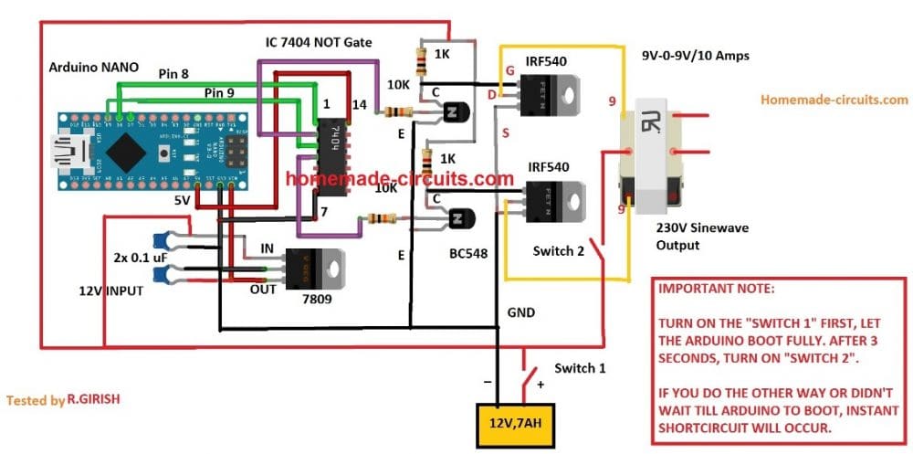
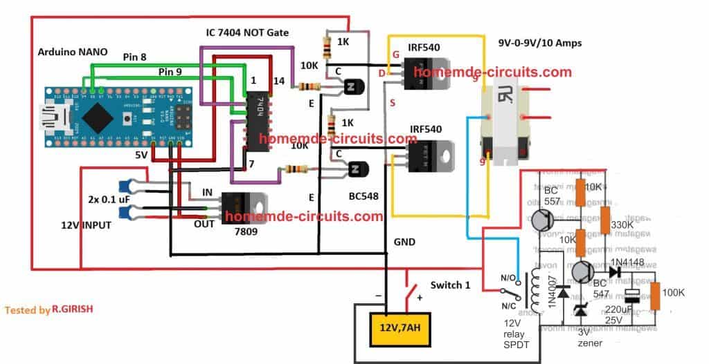
In the last article we learned how to generate sine wave pulse width modulation or SPWM though Arduino, we are going to use the same Arduino board to make the proposed simple pure sine wave inverter circuit.The design is actually extremely straightforward, as shown in the following figure.
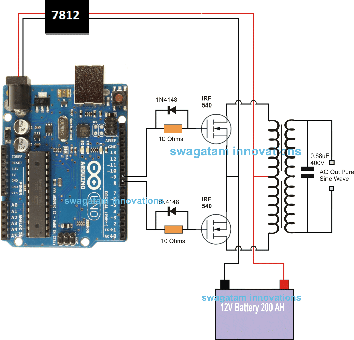
Pin#8 and pin#9 generate the spwms alternately and switch the relevant mosfets with the same SPWM pattern.
The mosfst in turn induce the transformer with high current SPWM waveform using the battery power, causing the secondary of the trafo to generate an identical waveform but at the main ac level
The proposed Arduino inverter circuit could be upgraded to any preferred higher wattage level, simply by upgrading the mosfets and the trafo rating accordingly, alternatively you can also convert this into a full bridge or an h-bridge sine wave inverter
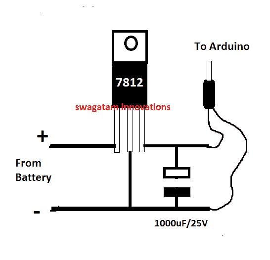
In the diagram the Arduino board could be seen supplied from a 7812 IC circuit, this could be built by wiring a standard 7812 ic in the following manner. The IC will ensure that the input to the Arduino never exceeds the 12V mark, although this might not be absolutely critical, unless the battery is rated over 18V.
If you have any questions regarding the above SPWM inverter circuit using a programmed Arduino, please feel free to ask them through your valuable comments.
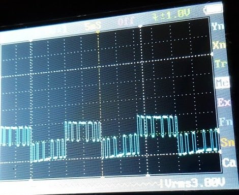
Image of SPWM waveform as obtained from the above Arduino inverter design (Tested and Submitted By Mr. Ainsworth Lynch)
For the Program Code please contact this number
UPDATE:
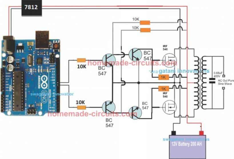
Since an Arduino board will produce a 5V output, it may not be an ideal value for driving mosfets directly.
Therefore an intermediate BJT level shifter stage may be required for raising the gate level to 12V so that the mosfets are able to operate correctly without causing unnecessary heating up of the devices,. The updated diagram (recommended) can be witnessed below:
Video Clip
Parts List
All resistors are 1/4 watt, 5% CFR
To ensure that the mosfet stage does not initiate during Arduino booting or start up, you may add the following delay generator and connect them at the base of the left side BC547 transistors. This will safeguard the mosfets and prevent them from burning during power switch ON Arduino booting.
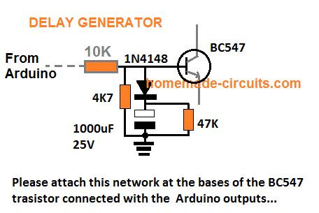
Just like any other inverter the output from this design can rise to unsafe limits when the battery is fully charged.
To control this an automatic voltage regulator could be employed as shown below.
The BC547 collectors should be connected to the bases of the left side BC547 pair, which are connected to the Arduino via 10K resistors.
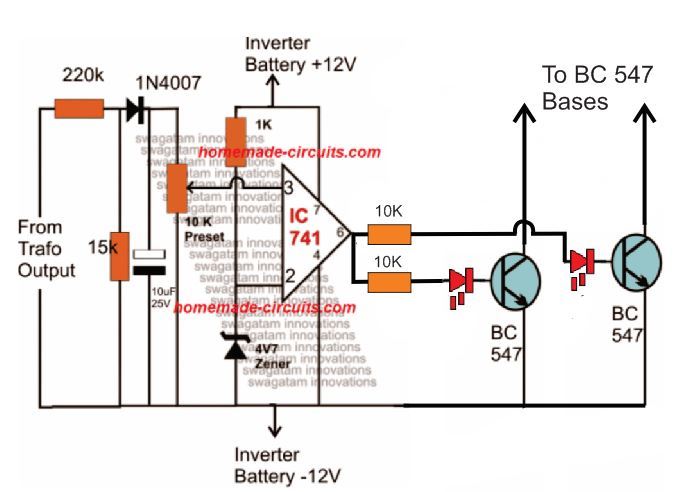
For an isolated version of voltage correction circuit we can modify the above circuit with a transformer, as shown below:
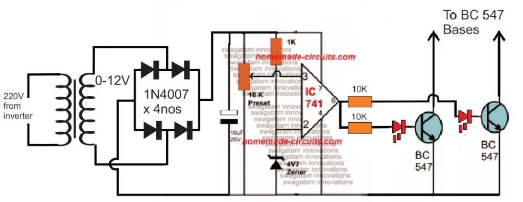
To set up the automatic voltage correction circuit, feed a stable 230V or 110V as per your inverter specs to the input side of the circuit.
Next, adjust the 10k preset carefully such that the red LEDs just light up. That's all, seal the preset and connect the circuit with the above Arduino board for implementing the intended automatic output voltage regulation.
Another design for the above Arduino sinewave inverter circuit can be seen below, the CMOS IC is used as an aided buffer for the BJT stage
Important:
In order to avoid an accidental switch ON prior to Arduino booting, a simple delay on the timer circuit may be included in the above design, as shown below:
In this post we learn how to generate sine wave pulse-width-modulation or SPWM through Arduino, which can be used for making a pure sine wave inverter circuit or similar gadgets.
The Arduino code is developed by me, and it is my first Arduino code, ...and it looks pretty good 🙂
Basically, SPWM which stands for sine wave pulse width modulation, is a type of pulse modulation where the pulses are modulated to simulate a sinusoidal waveform, so that the modulation is able to attain properties of a pure sine wave.
To implement a SPWM the pulses are modulated with an initial narrower widths which gradually get broader at the center of the cycle, and finally end being narrower at the end to finish the cycle.
To be more precise, the pulses begin with narrowest widths which gradually get broader with each subsequent pulses, and gets broadest at the center pulse, after this, the sequence continues on but with an opposite modulation, that is the pulses now gradually begin getting narrower until the cycle finishes.

Video Demo
This constitutes one SPWM cycle, and this repeats throughout at a particular rate as determined by the application frequency (usually 50Hz or 60Hz). Typically, SPWM is used for driving power devices such as mosfets or BJTs in inverters or converters.
This special modulation pattern ensures that the frequency cycles are executed with a gradually changing average voltage value (also called the RMS value) , instead of throwing sudden Hi/low voltage spikes as normally witnessed in flat square wave cycles.
This gradually modifying PWMs in a SPWM is purposely enforced so that it closely replicates the exponentially rising/falling pattern of a standard sinewaves or sinusoidal waveform, hence the name sinewave PWM or SPWM.
The above explained SPWM can be easily implemented using a few discrete parts, and also using Arduino which will probably enable you to get more accuracy with the waveform periods.
The following Arduino code can be used for implementing the intended SPWM for a given application.
Gosh!! that looks awfully big, if you know how to shorten it, you may certainly feel free to do it at y;
In the next post I'll explain how to use the above Arduino based SPWM generator to make a pure sinewave inverter circuit....keep reading!
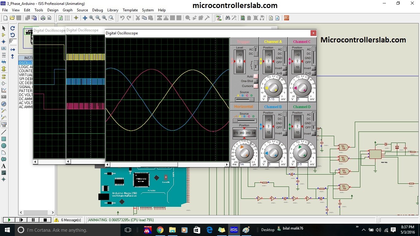
It is recommended to use it for high power applications. It can be designed using by connecting three single phase half full bridge converters. All three bridge should be operate such that all of them should be 120 degree out of phase with each other. Three phase sine wave inverter is designed using Arduino microcontroller. Arduino is used to generate SPWM singals to drive gate driver circuits as shown in figure below. These SPWM signal are 120 degree out of phase with each other. If you don’t know who to generate sinusoidal pulse width modulation signal, I recommend you read my article on SPWM generation using PIC microcontroller. After reading this article, you will get an idea about how to generate these signal to driver MOSFET drivers which are in turn used to drive MOSFET of three phase H bridge. Picture below shows the wave forms of gating signals which are 120 degree apart from each other. To completely understand working of this inverter, I recommend you to read any book on Power electronics.
Followings are the main components of three phase sine wave inverter:
So to design three phase sine wave inverter, you should know how to use above mentioned electronics components. But the most important thing is that you should have an idea about how to write program for it using microcontroller.
Watch the following video if you want to check results in proteus. Proteus will not simulate this circuit in real time due to high inductive and capactive components used. It will take some time for system to produce results due to excessive CPU lot
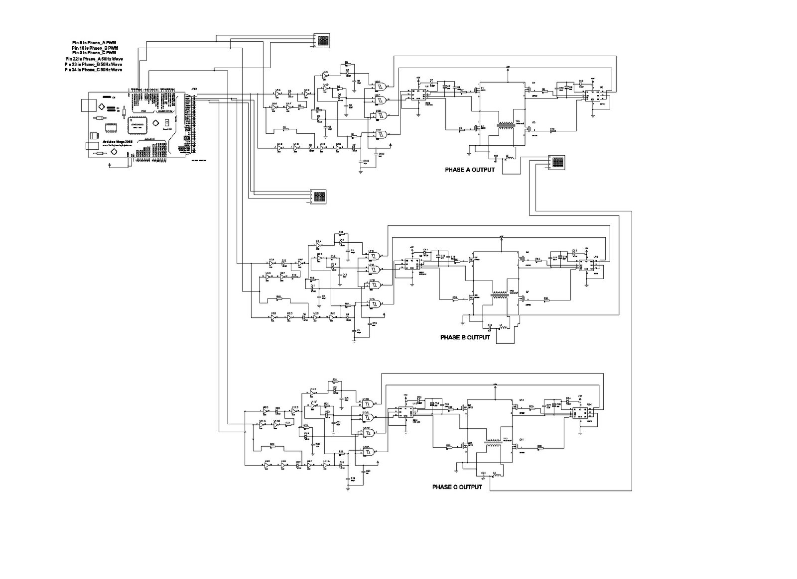
It circuit diagram is shown. It is a larger circuit diagram and it is difficult to display it properly in one picture, but still you can get an idea from this circuit diagram. I have used three single phase bridges to simulate this circuit in proteus but while implementing real time we have used only single three phase H bridge. you can use single three phase H bridge while real time implementation.
Code for three phase inverter is not free of cost. If you want to purchase code and simulation , you can buy with this whatsapp number. +2348106009848